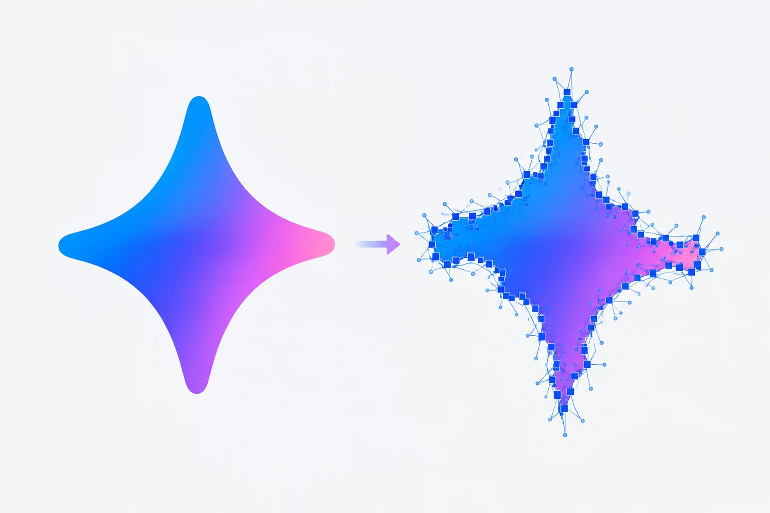
The Logo Looked Simple Until It Was Traced
Deconstructs unexpected node proliferation and perimeter jaggedness when transforming flat visual logos into production paths.
Explore cases about contrast, tiny details, interior openings, noisy edges, silhouettes, and the difference between source artwork and resulting vector shapes.
Examine our rigorous inspection of raster to vector workflows and Silhouette Studio trace outputs across challenging geometric assets. Each image trace study breaks down path topology, threshold sensitivity, and perimeter node densities.
Deconstructs unexpected node proliferation and perimeter jaggedness when transforming flat visual logos into production paths.
Examines how low-contrast texture grains unintentionally generate floating splinter polygons that disrupt cutter tracks.
Addresses collapsed counter spaces and lost internal cutouts caused by high default luminosity clamping parameters.
Need comprehensive assistance with raster to vector curve fidelity?
Comparing deterministic vectorization in sharp binary assets against boundary drift and node congestion in soft gradient sources. Understand how Silhouette Studio trace engines resolve boundary ambiguities.
Binary luminance profiles yield sharp transitions where the threshold detection algorithm locates unambiguous zero-crossing lines.
Diffuse falloffs and sub-pixel antialiasing force heuristic guessing, producing microscopic sawtooth rings and stray micro-polygons.
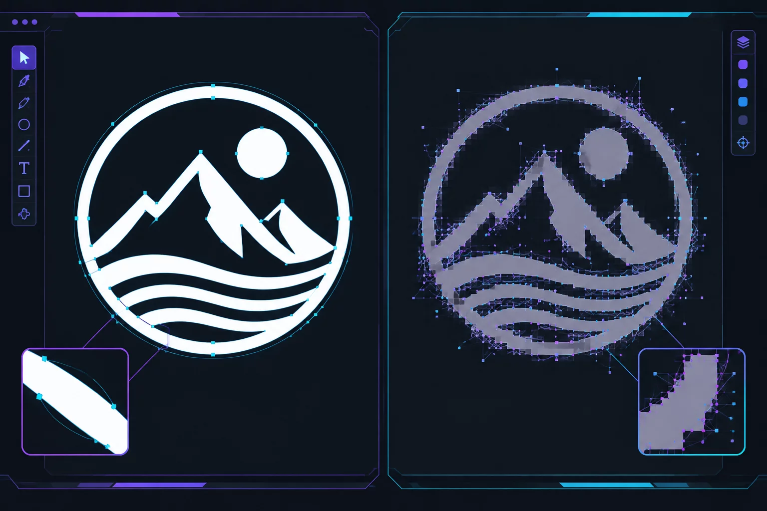
Under high contrast, clean vector silhouettes maintain mathematically stable tangent handles. As luminance deltas shrink below 18%, raster to vector modules misinterpret anti-aliased transitions as physical surface contours.
A step-by-step diagnostic of automated raster thresholding: how micro-contrast in organic venation generates fifty redundant cutting paths, and how to recover a clean, coherent silhouette.
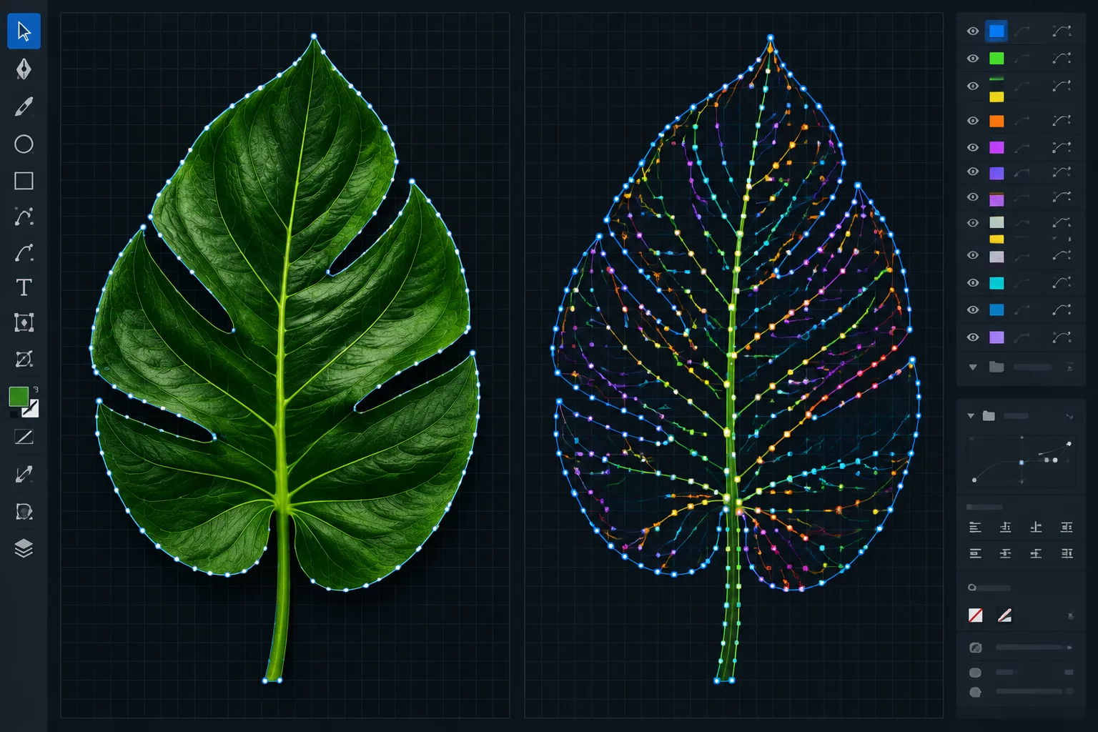
The starting file is a high-resolution bitmap of a botanical leaf. Chlorophyll distribution and drying veins create continuous tonal shifts across the surface, with soft edge transitions rather than binary black and white boundaries.
Every raster-to-vector conversion follows four deterministic validation gates. Discover the precise vector artifacts and diagnostic reports generated for review and sign-off at each operational phase.
Before algorithmic tracing commences, bitmap resolution, color quantization, and luminance levels are verified. Clients inspect side-by-side binary threshold previews to isolate signal from unwanted raster scan compression noise.
Initial raw tracing creates thousands of chaotic, jagged anchor points. In this phase, an interactive node overlay diagram is inspected to confirm path curve continuity, node reduction metrics, and the eradication of stair-stepped segments.
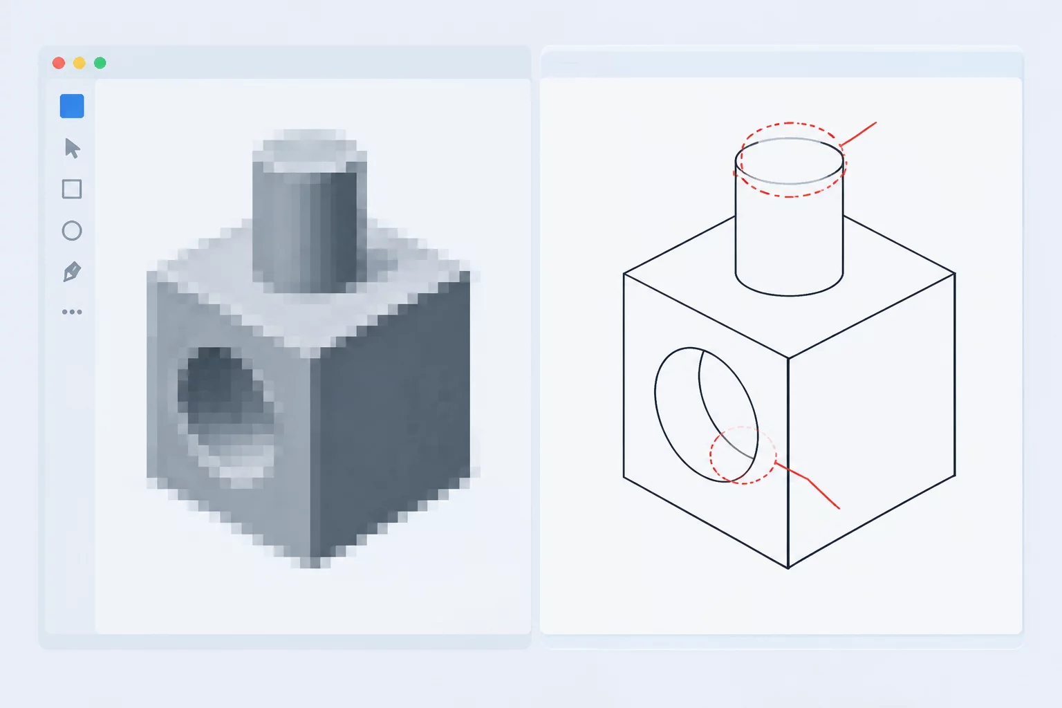
Automatic raster trace utilities routinely fill enclosed cavities or sever fine bridge junctions. At this stage, compound path structures and internal negative cutouts are isolated to confirm that counters in letters and decorative voids remain fully transparent.
The final clearance stage subjects the vectorized file to realistic blade trajectory simulation. Overlapping points, self-intersecting loops, and microscopic artifacts are inspected under full magnification prior to final format delivery.
To guarantee clean path geometry and prevent excessive anchor points in Silhouette Studio, review our baseline requirements before initiating vectorization work.
Provide uncompressed PNG, TIFF, or scan assets rendered at a minimum of 300 DPI. Blurry antialiased edges artificially generate chaotic node clusters during contour tracing.
Specify whether interior loops and closed inner counters should be preserved as compound cut-paths or flattened into a single solid outer silhouette mask.
Determine the threshold for curve smoothing versus strict angular fidelity. Cutting plotters require streamlined bezier curves with minimal anchor point counts.
State whether multi-tone illustrations require isolated vector layers per color plate or a unified monochrome contour suitable for standard vinyl plotting.
Define target physical scale (millimeters or inches). Detail retention decisions depend directly on whether an element is plotted at miniature scale or sign scale.
Confirm needed file formats compatible with your hardware workflow, including Silhouette Studio Studio3/DXF curves, SVG paths, or standard EPS formats.
Forward your source raster archives and path guidelines directly to our editorial studio team through the verified contact channel.

Automated graphic tracing often creates an illusion of simplicity. Designers and fabricators import a bitmap, execute a quick command, and expect production-ready curves. In practice, automated routines frequently fail silent structural standards.
Whether fine-tuning an intricate Silhouette Studio trace or diagnosing an automated image trace across contrasting line art, algorithmic defaults generate excessive anchor points and collapsed negative spaces. We created this notebook to demystify every phase of raster to vector conversion, giving practitioners reliable criteria to decide when an automated trace is salvageable and when manual drafting remains irreplaceable.
Examine how delicate bitmap silhouettes, noisy scan thresholds, and dense cluster fragments translate into production-ready bezier paths.
 INTERPRETATION
Analyzing missed silhouettes and interior geometry dropouts caused by aggressive tracing thresholds in raster to vector scans.
 INTERPRETATION
Detecting parasitic anchor clusters and artifact loops created from subtle edge degradation and bitmap noise.
 INTERPRETATION
Evaluating viable curves versus non-reconstructable segments during complex Silhouette Studio trace experiments.
 INTERPRETATION
Methods for preserving tiny fine-line elements without generating hundreds of unmanageable micro-anchor nodes.